-->

High Availability with Failover Clusters

Before moving on to the next chapter on my virtualization lab series, I think this might be a good opportunity to review some of the clustering options available today. I will use Windows Server Failover Clustering with Hyper-V because in today's world the trend is to combine Virtualization with High Availability (HA).

There are many ways to implement these solutions and the basic design concepts presented here can be adjusted to other virtualization platforms. Some of them will actually not guarantee a fault-tolerant solution, but most of them can be used in specific scenarios (even if only for demonstration purposes).

Two virtual machines on one physical server


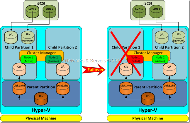
In this scenario an HA cluster is built between two (or more) virtual machines on a single physical machine. Here we have a single physical server running Hyper-V and two child partitions where you run Failover Clustering. This setup does not protect against hardware failures because when the physical server fails, both (virtual) cluster nodes will fail. Therefore, the physical machine itself is a single point of failure (SPOF).

Two virtual machines on one physical server
(Click to enlarge)

How to Setup a Virtualization Lab (III)

Failover Cluster Networking


The first step in the setup of a failover cluster is the creation of an AD domain because all the cluster nodes have to belong to the same domain. But before doing so, I changed the networks settings again in order to adjust them for this purpose.

LAB-DC:IP: 192.168.1.10
Gateway: 192.168.1.1 (Physical Router)
DNS: 127.0.0.1
Alternate DNS: 192.168.1.1

LAB-NODE1:
IP: 192.168.1.11
Gateway: 192.168.1.1
DNS: 192.168.1.10 (DC)
Alternate DNS: 192.168.1.1 (Physical Router)

LAB-NODE2:IP: 192.168.1.12
Gateway: 192.168.1.1
DNS: 192.168.1.10
Alternate DNS: 192.168.1.1

LAB-NODE3:
IP: 192.168.1.13
Gateway: 192.168.1.1
DNS: 192.168.1.10
Alternate DNS: 192.168.1.1

LAB-STORAGE:IP: 192.168.1.14
Gateway: 192.168.1.1
DNS: 192.168.1.10
Alternate DNS: 192.168.1.1

Therefore, I created a domain comprised of 5 machines; a DC and two member servers as Hyper-V VMs, a member server as a VMware VM and another member server as a VirtualBox VM.

So far I have demonstrated the possibility of integrating in the same logical infrastructure virtualized servers running on different platforms using different virtualization techniques; in this case we have VMs running in a Type 1 hypervisor (Hyper-V) and in two distinct Type 2 hypervisors (VMware Workstation and VirtualBox).

The option to create a network with static IP addresses is as valid as the alternative of using DHCP. Later on I plan to explore the several options provided by the cluster networking in Windows 2008 but for the time being I kept my network in a simple and basic configuration in order to proceed with the lab installation.

How to Setup a Virtualization Lab (II)


As mentioned at the end of my previous article, the installation of my lab continued with the creation of virtual machines on the desktop computer. But this time I used VMware and VirtualBox to explore the possibility of using a set of virtualized servers across different and competing virtualization technologies.

I insisted on the network configuration details because that is the basis of all the work ahead; a single virtual machine may be important but I want to show how they can work together and therefore the correct network configuration of paramount importance.

Import a Virtual Machine into VMware


I started by installing a VM on VMware Workstation. Better yet, I took advantage of what was previously done and used the generalized .vhd file I left behind! Since VMware does not directly support the use of .vhd files, I had to convert the file from the format used by Hyper-V (Virtual Hard Disk, i.e., .vhd) to the format used by VMware (Virtual Machine Disk, i.e., .vmdk).

The VMware vCenter Converter Standalone utility is a free application which can be obtained directly from VMware’s official site but doesn’t solve the problem as it doesn’t support this type of conversion, although it can convert from other formats and even directly from servers running Hyper-V. But what interested me was to use the work already done and so I resorted to the WinImage tool.

The process was very simple:

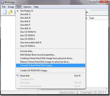
I selected the appropriate option from the Disk menu and select the proper source file;

WinImage


How to Setup a Virtualization Lab (I)


Now that I have concluded a general overview of most of the theory related to High Availability and Virtualization it is time to start testing some of those concepts and see them in action.

My goal for the next posts is to produce a series of tutorials showing how anyone can easily install a handful of virtual machines and be able to explore the wonderful possibilities provided by this technology. I will be using an old laptop powered by a Turion 64 X2 CPU with a 250 Gb SSD HD and 4 Gb of RAM combined with a desktop running Windows 7 Ultimate on a Athlon 64 X2 4800+ with 4 Gb of RAM and lots a free disk space scattered through 3 SATA hard drives.

Virtual Machines Creation


I will not go through the details of OS installation because I am assuming the ones reading these tutorials are way passed that.

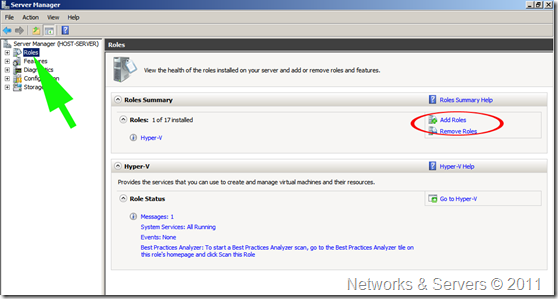
I started by installing a fresh copy of Windows Server 2008 R2 SP1 Standard on a secondary partition in my laptop.  Once I was done with the installation of all the available updates from Windows Update and with OS activation, I was ready to add the Hyper-V role in order to be able to install the virtual machines. To do this I just went into Server Manager/Roles, started the Add Roles Wizard, selected Hyper-V and followed the procedures. Nothing special so far, right?

Hyper-V Role

Note: All the pictures are clickable and will open a larger version in a separate window.

Scientists replicate brain using a chip

 
Scientists are getting closer to the dream of creating computer systems that can replicate the brain. Researchers at the Massachusetts Institute of Technology (MIT) have designed a computer chip that mimics how the brain's neurons adapt in response to new information. Such chips could eventually enable communication between artificially created body parts and the brain and it could also pave the way for artificial intelligence devices.

There are about 100 billion neurons in the brain, each of which forms synapses - the connections between neurons that allow information to flow - with many other neurons. This process is known as plasticity and is believed to underpin many brain functions, such as learning and memory.

Brain

Bacteria Inspire Robotics


Researchers at Tel Aviv University have developed a computational model that better explains how bacteria move in a swarm -- and this model can be applied to human-made technologies, including computers, artificial intelligence, and robotics. The team of scientists has discovered how bacteria collectively gather information about their environment and find an optimal path to growth, even in the most complex terrains.

Studying the principles of bacteria navigation will allow researchers to design a new generation of smart robots that can form intelligent swarms, aid in the development of medical micro-robots used to diagnose or distribute medications in the body, or "de-code" systems used in social networks and throughout the Internet to gather information on consumer behaviors.

Bacteria
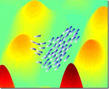
Simulated interacting agents collectively navigate towards a target (credit: American Friends of Tel Aviv University)

Hardware-Assisted Virtualization Explained


Hardware-assisted virtualization was first introduced on the IBM System/370 in 1972, for use with VM/370, the first virtual machine operating system. Virtualization was forgotten in the late 1970s but the proliferation of x86 servers rekindled interest in virtualization driven for the need for server consolidation; virtualization allowed a single server to replace multiple underutilized dedicated servers.

However, the x86 architecture did not meet the Popek and Goldberg Criteria to achieve the so called “classical virtualization″. To compensate for these limitations, virtualization of the x86 architecture has been accomplished through two methods: full virtualization or paravirtualization. Both create the illusion of physical hardware to achieve the goal of operating system independence from the hardware but present some trade-offs in performance and complexity.

Thus, Intel and AMD have introduced their new virtualization technologies, a handful of new instructions and — crucially — a new privilege level. The hypervisor can now run at "Ring -1"; so the guest operating systems can run in Ring 0.

Hardware virtualization leverages virtualization features built into the latest generations of CPUs from both Intel and AMD. These technologies, known as Intel VT and AMD-V respectively, provide extensions necessary to run unmodified virtual machines without the overheads inherent in full virtualization CPU emulation. In very simplistic terms these new processors provide an additional privilege mode below ring 0 in which the hypervisor can operate essentially leaving ring 0 available for unmodified guest operating systems.

A new quantum state of matter?


Researchers at the University of Pittsburgh have made advances in better understanding correlated quantum matter by studying topological states in order to advance quantum computing, a method that harnesses the power of atoms and molecules for computational tasks.

Through his research, W. Vincent Liu and his team have been studying orbital degrees of freedom and nano-Kelvin cold atoms in optical lattices (a set of standing wave lasers) to better understand new quantum states of matter. From that research, a surprising topological semimetal has emerged.

quantum

Since the discovery of the quantum Hall effect by Klaus Van Klitzing in 1985, researchers like Liu have been particularly interested in studying topological states of matter, that is, properties of space unchanged under continuous deformations or distortions such as bending and stretching. The quantum Hall effect proved that when a magnetic field is applied perpendicular to the direction a current is flowing through a metal, a voltage is developed in the third perpendicular direction. Liu's work has yielded similar yet remarkably different results.

"We never expected a result like this based on previous studies," said Liu. "We were surprised to find that such a simple system could reveal itself as a new type of topological state -- an insulator that shares the same properties as a quantum Hall state in solid materials."
"This new quantum state is very reminiscent of quantum Hall edge states," said Liu. "It shares the same surface appearance, but the mechanism is entirely different: This Hall-like state is driven by interaction, not by an applied magnetic field."

Liu says this liquid matter could potentially lead toward topological quantum computers and new quantum devices for topological quantum telecommunication. Next, he and his team plan to measure quantities for a cold-atom system to check these predicted quantum-like properties.

Operating System-Level Virtualization Explained


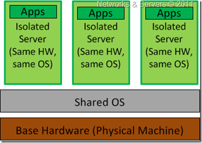
This kind of server virtualization is a technique where the kernel of an operating system allows for multiple isolated user-space instances. These instances run on top of an existing host operating system and provide a set of libraries that applications interact with, giving them the illusion that they are running on a machine dedicated to its use. The instances are known as Containers, Virtual Private Servers or Virtual Environments.

Operating System-Level Virtualization

Operating system level virtualization is achieved by the host system running a single OS kernel and through its control of guest operating system functionality. Under this shared kernel virtualization the virtual guest systems each have their own root file system but share the kernel of the host operating system.

Paravirtualization Explained


“Para“ is an English affix of Greek origin that means "beside," "with," or "alongside.” Paravirtualization is another approach to server virtualization where, rather than emulate a complete hardware environment, paravirtualization acts as a thin layer, which ensures that all of the guest operating systems share the system resources and work well together.

Paravirtualization

Under paravirtualization, the kernel of the guest operating system is modified specifically to run on the hypervisor. This typically involves replacing any privileged operations that will only run in ring 0 of the CPU, with calls to the hypervisor (known as hypercalls). The hypervisor in turn performs the task on behalf of the guest kernel and also provides hypercall interfaces for other critical kernel operations such as memory management, interrupt handling and time keeping.

Full Virtualization Explained


This is probably the most common and most easily explained kind of server virtualization. When IT departments were struggling to get results with machines at full capacity, it made sense to assign one physical server to every IT function taking advantage of cheap hardware A typical enterprise would have one box for SQL, one for the Apache server and another physical box for the Exchange server. Now, each of those machines could be using only 5% of its full processing potential. This is where hardware emulators come into play in an effort to consolidate those servers.

A hardware emulator presents a simulated hardware interface to guest operating systems. In hardware emulation, the virtualization software (usually referred to as a hypervisor) actually creates an artificial hardware device with everything it needs to run an operating system and presents an emulated hardware environment that guest operating systems operate upon. This emulated hardware environment is typically referred to as a Virtual Machine Monitor or VMM.

Hardware emulation supports actual guest operating systems; the applications running in each guest operating system are running in truly isolated operating environments. This way, we can have multiple servers running on a single box, each completely independent of the other. The VMM provides the guest OS with a complete emulation of the underlying hardware and for this reason, this kind of virtualization is also referred to as Full Virtualization.


Thus, full virtualization provides a complete simulation of the underlying hardware and is a technique used to provide support for unmodified guest operating systems. This means that all software, operating systems and applications, which can run natively on the hardware can also be run in the virtual machine.

The term unmodified refers to operating system kernels which have not been altered to run on a hypervisor and therefore still execute privileged operations as though running in ring 0 of the CPU. Full virtualization uses the hypervisor to coordinate the CPU of the server and the host machine's system resources in order to manage the running of guest operating systems without any modification. In this scenario, the hypervisor provides CPU emulation to handle and modify privileged and protected CPU operations made by unmodified guest operating system kernels.

The guest operating system makes system calls to the emulated hardware. These calls, which would actually interact with underlying hardware, are intercepted by the virtualization hypervisor which maps them onto the real underlying hardware. The hypervisor provides complete independence and autonomy of each virtual server to other virtual servers running on the same physical machine. Each guest server has its own operating system and it may even happen that one guest server is running Linux and the other is running Windows.

The hypervisor also monitors and controls the physical server resources, allocating what is needed to each operating system and making sure that the guest operating systems (the virtual machines) cannot disrupt each other. With full virtualization, the guest OS is not aware it is being virtualized and thus requires no modification.

Type 1 Hypervisor


Also known as Native or Bare-Metal Virtualization, this is a technique where the abstraction layer sits directly on the hardware and all the other blocks reside on top of it. The Type 1 hypervisor runs directly on the hardware of the host system in ring 0. The task of this hypervisor is to handle resource and memory allocation for the virtual machines in addition to providing interfaces for higher level administration and monitoring tools.The operating systems run on another level above the hypervisor.

Type 1 Hypervisor

Clearly, with the hypervisor occupying ring 0 of the CPU, the kernels for any guest operating systems running on the system must run in less privileged CPU rings. The Type 1 Hypervisor contains functionalities like CPU scheduling and Memory Management and, even though there is no Host OS, usually one of the Virtual Machines has certain privileged status (Control/Admin/Parent VM).

Unfortunately, most operating system kernels are written explicitly to run in ring 0 for the simple reason that they need to perform tasks that are only available in that ring, such as the ability to execute privileged CPU instructions and directly manipulate memory.
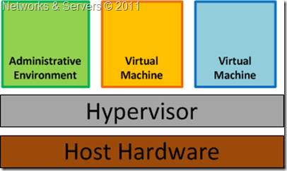
Bare-Metal Virtualization

Also, depending on the architecture, the hypervisor may either contain the drivers for the hardware resources (referred to as a Monolithic Hypervisor) or the drivers may be retained at the Guest OS level itself (in which case it can be called a Microkernelized Hypervisor).

Hypervisors

Since it has low level direct access to the hardware, a Type 1 hypervisor is more efficient than a hosted application and delivers greater performance because it uses fewer resources (no separate CPU cycles or memory footprint as in the case of a full-fledged Host OS).

The disadvantage of this model is that there is dependency on the hypervisor for the drivers (at least in case of the Monolithic Hypervisor). Besides, most implementations of the bare-metal approach require specific virtualization support at the hardware level (“Hardware-assisted”, to be discussed in a future post).

Examples of this architecture are Microsoft Hyper-V and VMware ESX Server.

Note: Microsoft Hyper-V (released in June 2008) exemplifies a Type 1 product that can be mistaken for a Type 2. Both the free stand-alone version and the version that is part of the commercial Windows Server 2008 product use a virtualized Windows Server 2008 parent partition to manage the Type 1 Hyper-V hypervisor. In both cases the Hyper-V hypervisor loads prior to the management operating system, and any virtual environments created run directly on the hypervisor, not via the management operating system.

Type 2 Hypervisor


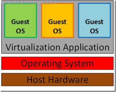
Guest OS Virtualization is perhaps the easiest concept to understand. In this scenario the physical host computer system runs a standard unmodified operating system such as Windows, Linux, Unix or MacOS X, and the virtualization layer runs on top of that OS being in effect a hosted application. In this architecture, the VMM provides each virtual machine with all the services of the physical system, including a virtual BIOS, virtual devices and virtual memory. This has the effect of making the guest system think it is running directly on the system hardware, rather than in a virtual machine within an application.

The OS itself provides the abstraction layer (known as Type 2 Hypervisor), such that it allows other OSes to reside within; thus creating virtual machines. This architecture then can be called as Hosted Virtualization (since an OS is ‘hosting’ it), as depicted below.
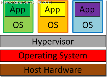
Type 2 Hypervisor

The virtualization layer in the above figure contains the software needed for hosting and managing the virtual machines but its exact functionality can vary based on the different architectures from different vendors. In this approach, the Guest OS relies on the underlying Host OS for access to the hardware resources.
image
The multiple layers of abstraction between the guest operating systems and the underlying host hardware are not conducive to high levels of virtual machine performance. This technique does, however, have the advantage that no changes are necessary to either host or guest operating systems and no special CPU hardware virtualization support is required.

Examples of a Type 2 Hypervisor are Oracle's VirtualBox, VMware Server, VMware Workstation and Microsoft Virtual PC.

Embedded Hypervisor


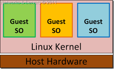
In Kernel Level Virtualization the host operating system runs on a specially modified kernel which contains extensions designed to manage and control multiple virtual machines each containing a guest operating system.

The virtualization layer is embedded into an operating system kernel and each guest runs its own kernel, although restrictions apply in that the guest operating systems must have been compiled for the same hardware as the kernel in which they are running.
Embedded Hypervisor

The real benefit with this approach is that the hypervisor code is dramatically leaner than either Type 1 or Type 2. With the hypervisor embedded into the Linux kernel, the guest operating systems benefit from excellent disk and network I/O performance.

Examples of kernel level virtualization technologies include User Mode Linux (UML) and Kernel-based Virtual Machine (KVM).

Full Virtualization Advantages


  • This approach to virtualization means that applications run in a truly isolated guest OS, with one or more of these guest OSs running simultaneously on the same hardware. Not only does this method support multiple OSes, it can support dissimilar OSes, differing in minor ways (for example, version and patch level) or in major ways (for example, completely different OSes like Windows and Linux);

  • The guest OS is not aware it is being virtualized and requires no modification. Full virtualization is the only option that requires no hardware assist or operating system assist to virtualize sensitive and privileged instructions. The hypervisor translates all operating system instructions on the fly and caches the results for future use, while user level instructions run unmodified at native speed;

  • The VMM provides a standardized hardware environment that the guest OS resides on and interacts with. Because the guest OS and the VMM form a consistent package, that package can be migrated from one machine to another, even though the physical machines the packages run upon may differ;

  • Full virtualization offers the best isolation and security for virtual machines, and simplifies migration and portability as the same guest OS instance can run virtualized or on native hardware.

Full Virtualization Limitations


  • The virtualization software hurts performance, which is to say that applications often run somewhat slower on virtualized systems than if they were run on unvirtualized systems. The hypervisor needs data processing, which means that part of the computing power of a physical server and related resources should be reserved for the hypervisor program. While the VMMs appears to solve the entire problem with regard to virtualized machines, it does bring in some level of performance degradation, caused by the extra processing (in terms of the ‘instruction translation’) that the hypervisor has to do. This can have a negative impact on overall server performance and slow down the applications;

  • The hypervisor must contain the interfaces to the resources of the machine; these interfaces are referred to as device drivers. Because hardware emulation uses software to trick the guest OS into communicating with simulated non-existent hardware, this approach has created some driver compatibility problems. The issue is that the hypervisor contains the device drivers and it might be difficult for new device drivers to be installed by users (unlike on your typical PC). Consequently, if a machine has hardware resources the hypervisor has no driver for, the virtualization software can’t be run on that machine. This can cause problems, especially for organizations that want to take advantage of new hardware developments.
Quantum cryptography breached?

Quantum cryptography has been pushed onto the market as a way to provide absolute security for communications and, as far as we know, no current quantum cryptographic system has been compromised in the field. It is already used in Swiss elections to ensure that electronic vote data is securely transmitted to central locations.

Quantum cryptography relies on the concept of entanglement. With entanglement, some statistical correlations are measured to be larger than those found in experiments based purely on classical physics. Cryptographic security works by using the correlations between entangled photons pairs to generate a common secret key. If an eavesdropper intercepts the quantum part of the signal, the statistics change, revealing the presence of an interloper.

The Swiss general approach can be summed up as follows: if you can fool a detector into thinking a classical light pulse is actually a quantum light pulse, then you might just be able to defeat a quantum cryptographic system. But even then the attack should fail, because quantum entangled states have statistics that cannot be achieved with classical light sources—by comparing statistics, you could unmask the deception.

But there's a catch here. I can make a classical signal that is perfectly correlated to any signal at all, provided I have time to measure said signal and replicate it appropriately. In other words, these statistical arguments only apply when there is no causal connection between the two measurements.

You might think that this makes intercepting the quantum goodness of a cryptographic system easy. But you would be wrong. When Eve intercepts the photons from the transmitting station run by Alice, she also destroys the photons. And even though she gets a result from her measurement, she cannot know the photons' full state. Thus, she cannot recreate, at the single photon level, a state that will ensure that Bob, at the receiving station, will observe identical measurements.


That is the theory anyway. But this is where the second loophole comes into play. We often assume that the detectors are actually detecting what we think they are detecting. In practice, there is no such thing as a single photon, single polarization detector. Instead, what we use is a filter that only allows a particular polarization of light to pass and an intensity detector to look for light. The filter doesn't care how many photons pass through, while the detector plays lots of games to try and be single photon sensitive when, ultimately, it is not. It's this gap between theory and practice that allows a carefully manipulated classical light beam to fool a detector into reporting single photon clicks.

Since Eve has measured the polarization state of the photon, she knows what polarization state to set on her classical light pulse in order to fake Bob into recording the same measurement result. When Bob and Alice compare notes, they get the right answers and assume everything is on the up and up.
The researchers demonstrated that this attack succeeds with standard (but not commercial) quantum cryptography equipment under a range of different circumstances. In fact, they could make the setup outperform the quantum implementation for some particular settings.

(Adapted from ArsTechnica)

Software to Prevent Child Abuse

Investigators estimate that there are currently more than 15 million photographs and videos of child abuse victims circulating on the Internet, or in the Darknet. By the time this material has been tracked down and deleted, pedophiles have long since downloaded it to their computers. Seeking and tracking hundreds of thousands of illegal media files in the suspect’s computer was tedious and extremely time-consuming process for investigators, until now.

Researchers from Fraunhofer Institute come up with an automated assistance system, called “desCRY”, that can detect child-pornographic images and video, from among even large volumes of data.
 
desCRY search results

The desCRY software uses novel pattern-recognition processes to navigate through digital photos and videos in search of illegal content, no matter how well-hidden it may be. The heart of the software consists of intelligent pattern-recognition algorithms that automatically analyze and classify images and video sequences combining technologies such as facial and skin-tone recognition with contextual and scene analyses to identify suspicious content.

The software searches all of the files in a computer, e-mail attachments and archives included and has many types of filtering allowing for a wide variety of search options. It can perform content-based data sorting and filtering, for instance. This way, investigators can sort files by person, object or location, for example. 
The algorithms use up to several thousand characteristics that describe properties such as color, texture and contours in order to analyze whether an image depicts child abuse. If the system is run on a standard PC, it classifies up to ten images per second, drastically accelerating the investigation works.

Quantum Cloning Advances

Quantum cloning is the process that takes an arbitrary, unknown quantum state and makes an exact copy without altering the original state in any way. Quantum cloning is forbidden by the laws of quantum mechanics as shown by the no cloning theorem. Though perfect quantum cloning is not possible, it is possible to perform imperfect cloning, where the copies have a non-unit fidelity with the state being cloned.

The quantum cloning operation is the best way to make copies of quantum information therefore cloning is an important task in quantum information processing, especially in the context of quantum cryptography. Researchers are seeking ways to build quantum cloning machines, which work at the so called quantum limit. Quantum cloning is difficult because quantum mechanics laws only allow for an approximate copy—not an exact copy—of an original quantum state to be made, as measuring such a state prior to its cloning would alter it. The first cloning machine relied on stimulated emission to copy quantum information encoded into single photons.

Scientists in China have now produced a theory for a quantum cloning machine able to produce several copies of the state of a particle at atomic or sub-atomic scale, or quantum state. A team from Henan Universities in China, in collaboration with another team at the Institute of Physics of the Chinese Academy of Sciences, have produced a theory for a quantum cloning machine able to produce several copies of the state of a particle at atomic or sub-atomic scale, or quantum state. The advance could have implications for quantum information processing methods used, for example, in message encryption systems.

In this study, researchers have demonstrated that it is theoretically possible to create four approximate copies of an initial quantum state, in a process called asymmetric cloning. The authors have extended previous work that was limited to quantum cloning providing only two or three copies of the original state. One key challenge was that the quality of the approximate copy decreases as the number of copies increases.

The authors were able to optimize the quality of the cloned copies, thus yielding four good approximations of the initial quantum state. They have also demonstrated that their quantum cloning machine has the advantage of being universal and therefore is able to work with any quantum state, ranging from a photon to an atom. Asymmetric quantum cloning has applications in analyzing the security of messages encryption systems, based on shared secret quantum keys.

Server Virtualization Explained


You have probably heard about lots of distinct types of server virtualization; full, bare metal, para-virtualization, guest OS, OS assisted, hardware assisted, hosted, OS level, kernel level, shared kernel, hardware emulation, hardware virtualization, hypervisor based, containers or native virtualization. Confusing, right?

Fear not my faithful readers; the whole purpose of this blog is exactly to explain these things so that everyone can have a clear view over issues usually restricted to a bunch of geeks. But keep in mind that some of these terms are popularized by certain vendors and do not have a common industry-wide acceptance. Plus, many of the terms are used rather loosely and interchangeably (which is why they are so confusing).

Although others classify the current virtualization techniques in a different way, I will use the following criteria:

  1. Full Virtualization;
  2. Para-Virtualization;
  3. Operating System-level Virtualization;
  4. Hardware assisted virtualization.

On the following exciting chapters I will explain these techniques, one by one, but before that I believe it would be useful to give you a quick introduction to some underlying concepts.

Virtualization (III)


Server Virtualization


Out of all three of the different types of virtualization discussed in this blog, I believe that server virtualization is the type of virtualization everybody is most familiar with. When people say "virtualization", they are usually referring to server virtualization because this is the main area of virtualization, whereby a number of “virtual machines” are created on one server meaning that multiple tasks can then be assigned to the one server, saving on processing power, cost and space.

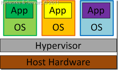
Server virtualization inserts a layer of abstraction between the physical server hardware and the software that runs on the server allowing us to run multiple guest computers on a single host computer with those guest computers believing they are running on their own hardware. The physical machine is translated into one or more virtual machines (VMs). Each VM runs its own operating system and applications, and each utilizes some allocated portion of the server's processing resources such as CPU, memory, network access and storage I/O. This means that any network tasks that are happening on the server still appear to be on a separate space, so that any errors can be diagnosed and fixed quickly.

Server Virtualization

By doing this, we gain all the benefits of any type of virtualization: portability of guest virtual machines, reduced operating costs, reduced administrative overhead, server consolidation, testing & training, disaster recovery benefits, and more.

Virtualization (II)


Network Virtualization


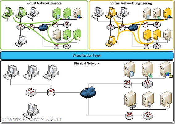
When we think of network virtualization, we always think of VLANs but there is much more to network virtualization than just VLANs. Network virtualization is when all of the separate resources of a network are combined, allowing the administrator to share them out amongst the users of the network. Thus, it is a method of combining the available resources in a network by splitting up the available bandwidth into channels, each of which is independent from the others, and each of which can be assigned (or reassigned) to a particular server or device in real time. This allows each user to access all of the network resources from their computer either they are files and folders on the computer, printers or hard drives etc.

Network Virtualization

The theory behind network virtualization is to take many of the traditional client/server based services and put them "on the network". Certain vendors advertise virtualization and networking as a vehicle for additional services and not just as a way to aggregate and allocate network resources. For example, it's common practice for routers and switches to support security, storage, voice over IP (VoIP), mobility and application delivery.

One network vendor actually has a working card that is inserted into a router. On that card is a fully-functioning Linux server that has a connection to the backbone of the router. On that Linux server, you can install applications like packet sniffers, VoIP, security applications, and many more.
Network virtualization provides an abstraction layer that decouples physical network devices from operating systems, applications and services delivered over the network allowing them to run on a single server or for desktops to run as virtual machines in secure data centers, creating a more agile and efficient infrastructure. This streamlined approach makes the life of the network administrator much easier, and it makes the system seem much less complicated to the human eye than it really is.

Network virtualization is a versatile technology. It allows you to combine multiple networks into a single logical network, parcel a single network into multiple logical networks and even create software-only networks between virtual machines (VMs) on a physical server. Virtual networking typically starts with virtual network software, which is placed outside a virtual server (external) or inside a virtual server, depending on the size and type of the virtualization platform.

Virtualization (I)


Virtualization is a massively growing aspect of computing and IT creating "virtually" an unlimited number of possibilities for system administrators. Virtualization has been around for many years in some form or the other, the trouble with it, is being able to understand the different types of virtualization, what they offer, and how they can help us.

Virtualization has been defined as the abstraction of computer resources or as a technique for hiding the physical characteristics of computing resources from the way in which other systems, applications, or end users interact with those resources. In fact, virtualization always means abstraction. We make something transparent by adding layers that handle translations, causing previously important aspects of a system to become moot.

Storage Virtualization


The amount of data organizations are creating and storing is rapidly increasing due to the shift of business processes to Web-based digital applications and this huge amount of data is causing problems for many of them. First, many applications generate more data than can be stored physically on a single server. Second, many applications, particularly Internet-based ones, have multiple machines that need to access the same data. Having all of the data sitting on one machine can create a bottleneck, not to mention presenting risk from the situation where many machines might be made inoperable if a single machine containing all the application’s data crashes. Finally, the increase in the number of machines causes backup problems because trying to create safe copies of data is a tremendous task when there are hundreds or even thousands of machines that need data backup.

For these reasons, data has moved into virtualization. Companies use centralized storage (virtualized storage) as a way of avoiding data access problems. Furthermore, moving to centralized data storage can help IT organizations reduce costs and improve data management efficiency. The basic premise of storage virtualization solutions is not new. Disk storage has long relied on partitioning to organize physical disk tracks and sectors into clusters, and then abstract clusters into logical drive partitions (e.g., the C: drive). This allows the operating system to read and write data to the local disks without regard to the physical location of individual bytes on the disk platters.
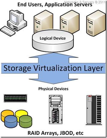
Storage virtualization creates a layer of abstraction between the operating system and the physical disks used for data storage. The virtualized storage is then location-independent, which can enable more efficient use and better storage management. For example, the storage virtualization software or device creates a logical space, and then manages metadata that establishes a map between the logical space and the physical disk space. The creation of logical space allows a virtualization platform to present storage volumes that can be created and changed with little regard for the underlying disks.

Storage Virtualization Layer

The storage virtualization layer is where the resources of many different storage devices are pooled so that it looks like they are all one big container of storage. This is then managed by a central system that makes it all look much simpler to the network administrators. This is also a great way to monitor resources, as you can then see exactly how much you have left at a given time giving much less hassle when it comes to backups etc.

In most data centers, only a small percentage of storage is used because, even with a SAN, one has to allocate a full disk logical unit number (LUN) to the server (or servers) attaching to that LUN. Imagine that a LUN fills up but there is disk space available on another LUN. It is very difficult to take disk space away from one LUN and give it to another LUN. Plus, it is very difficult to mix and match storage and make it appear all as one.
 Storage Virtualization

Storage virtualization works great for mirroring traffic across a WAN and for migrating LUNs from one disk array to another without downtime. With some types of storage virtualization, for instance, you can forget about where you have allocated data, because migrating it somewhere else is much simpler. In fact, many systems will migrate data based on utilization to optimize performance.

High Availability Storage (II)


Storage Area Network


A Storage Area Network (SAN) is a dedicated high-performance subnet that provides access to consolidated, block level data storage and is primarily used to transfer data between computer systems and storage elements and among multiple storage elements, making storage devices, such as disk arrays, tape libraries, and optical jukeboxes, accessible to servers so that the devices appear like locally attached devices to the operating system.

Storage Area Network

A SAN typically has its own communication infrastructure that is generally not accessible through the local area network by other devices. A SAN moves data among various storage devices, allowing for the sharing data between different servers, and provides a fast connection medium for backing up, restoring, archiving, and retrieving data. SAN devices are usually installed closely in a single room, but they can also be connected over long distances, making it very useful to large companies.

SAN Benefits


The primary benefits of a SAN are:

  • High Availability: One copy of every piece of data is always accessible to any and all hosts via multiple paths;
  • Reliability: Dependable data transportation ensures a low error rate, and fault tolerance capabilities;
  • Scalability: Servers and storage devices may be added independently of one another and from any proprietary systems;
  • Performance: Fibre Channel (the standard method for SAN interconnectivity) has now over than 2000MB/sec bandwidth and low overhead, and it separates storage and network I/O;

High Availability Storage (I)


RAID Concepts


The acronym RAID stands for Redundant Array of Inexpensive Disks and is a technology that provides increased storage functions and reliability through redundancy. It was developed using a large number of low cost hard drives linked together to form a single large capacity storage device that offered superior performance, storage capacity and reliability over older storage systems. This was achieved by combining multiple disk drive components into a logical unit, where data was distributed across the drives in one of several ways called "RAID levels".
This concept of storage virtualization and was first defined as Redundant Arrays of Inexpensive Disks but the term later evolved into Redundant Array of Independent Disks as a means of dissociating a low-cost expectation from RAID technology.
There are two primary reasons that RAID was implemented:
  • Redundancy: This is the most important factor in the development of RAID for server environments. A typical RAID system will assure some level of fault tolerance by providing real time data recovery with uninterrupted access when hard drive fails;

  • Increased Performance: The increased performance is only found when specific versions of the RAID are used. Performance will also be dependent upon the number of drives used in the array and the controller;

Hardware-based RAID


When using hardware RAID controllers, all algorithms are generated on the RAID controller board, thus freeing the server CPU. On a desktop system, a hardware RAID controller may be a PCI or PCIe expansion card or a component integrated into the motherboard. These are more robust and fault tolerant than software RAID but require a dedicated RAID controller to work.

Hardware implementations provide guaranteed performance, add no computational overhead to the host computer, and can support many operating systems; the controller simply presents the RAID array as another logical drive

Software-based RAID


Many operating systems provide functionality for implementing software based RAID systems where the OS generate the RAID algorithms using the server CPU. In fact the burden of RAID processing is borne by a host computer's central processing unit rather than the RAID controller itself which can severely limit the RAID performance.

Although cheap to implement it does not guarantee any kind of fault tolerance; should a server fail the whole RAID system is lost.

Hot spare drive


Both hardware and software RAIDs with redundancy may support the use of hot spare drives, a drive
physically installed in the array which is inactive until an active drive fails. The system then automatically replaces the failed drive with the spare, rebuilding the array with the spare drive included. This reduces the mean time to recovery (MTTR), but does not completely eliminate it. Subsequent additional failure(s) in the same RAID redundancy group before the array is fully rebuilt can result in data loss. Rebuilding can take several hours, especially on busy systems.

Failover Clustering (IV)


Cluster Node Configurations


The most common size for an high availability cluster is a two-node cluster, since that's the minimum required to assure redundancy, but many clusters consist of many more, sometimes dozens of nodes and such configurations can be categorized into one of the following models:

Active/Passive Cluster


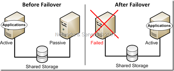
In an Active/Passive (or asymmetric) configuration, applications run on a primary, or master, server. A dedicated redundant server is present to take over on any failure but apart from that it is not configured to perform any other functions. Thus, at any time, one of the nodes is active and the other is passive. This configuration provides a fully redundant instance of each node, which is only brought online when its associated primary node fails.
The active/passive cluster generally contains two identical nodes. Database applications single instances are installed on both nodes, but the database is located on shared storage. During normal operation, the database instance runs only on the active node. In the event of a failure of the currently active primary system, clustering software will transfer control of the disk subsystem to the secondary system. As part of the failover process, the database instance on the secondary node is started, thereby resuming the service.
 
Active/Passive Cluster

This configuration is the simplest and most reliable but typically requires the most extra hardware.

Failover Clustering (III)


Cluster Quorum Configurations


In simple terms, the quorum for a cluster is the number of elements that must be online for that cluster to continue running. Server clusters require a quorum resource to function and this, like any other resource, is a resource which can only be owned by one server at a time, and for which servers can negotiate for ownership. In effect, each element can cast one “vote” to determine whether the cluster continues running. The voting elements are nodes or, in some cases, a disk witness or file share witness. The quorum resource is used to store the definitive copy of the cluster configuration so that regardless of any sequence of failures, the cluster configuration will always remain consistent. Each voting element (with the exception of a file share witness) contains a copy of the cluster configuration, and the Cluster service works to keep all copies synchronized at all times.

When network problems occur, they can interfere with communication between cluster nodes. A small set of nodes might be able to communicate together across a functioning part of a network but not be able to communicate with a different set of nodes in another part of the network. This can cause serious issues. In this "split" situation, at least one of the sets of nodes must stop running as a cluster.
Negotiating for the quorum resource allows Server clusters to avoid "split-brain" situations where the servers are active and think the other servers are down.
To prevent the issues that are caused by a split in the cluster, the cluster software requires that any set of nodes running as a cluster must use a voting algorithm to determine whether, at a given time, that set has quorum. Because a given cluster has a specific set of nodes and a specific quorum configuration, the cluster will know how many "votes" constitutes a majority (that is, a quorum). If the number drops below the majority, the cluster stops running. Nodes will still listen for the presence of other nodes, in case another node appears again on the network, but the nodes will not begin to function as a cluster until the quorum exists again.

Failover Clustering (II)


The failover mechanism


In the cluster, shared resources can be seen from all computers, or nodes. Each node automatically senses if another node in the cluster has failed, and processes running on the failed node continue to run on an operational one. To the user, this failover is usually transparent. Depicted in the next figure is a two-node cluster; both nodes have local disks and shared resources available to both computers. The heartbeat connection allows the two computers to communicate and detects when one fails; if Node 1 fails, the clustering software will seamlessly transfer all services to Node 2.
 
The failover mechanism
 
The Windows service associated with the failover cluster named Cluster Service has a few components:
  • Event processor;
  • Database manager;
  • Node manager;
  • Global update manager
  • Communication manager;
  • Resource (or failover) manager.
The resource manager communicates directly with a resource monitor that talks to a specific application DLL that makes an application cluster-aware. The communication manager talks directly to the Windows Winsock layer (a component of the Windows networking layer).
The failover process is as follows:

Failover Clustering (I)

Clustering Basics


Clustering is the use of multiple computers and redundant interconnections to form what appears to be a single, highly available system. A cluster provides protection against downtime for important applications or services that need to be always available by distributing the workload among several computers in such a way that, in the event of a failure in one system, the service will be available on another.

The basic concept of a cluster is easy to understand; a cluster is two or more systems working in concert to achieve a common goal. Under Windows, two main types of clustering exist: scale-out/availability clusters known as Network Load Balancing (NLB) clusters, and strictly availability-based clusters known as failover clusters. Microsoft also has a variation of Windows called Windows Compute Cluster Server.

When a computer unexpectedly falls or is intentionally taken down, clustering ensures that the processes and services being run switch to another machine, or "failover," in the cluster. This happens without interruption or the need for immediate admin intervention providing a high availability solution, which means that critical data is available at all times.
Failover Cluster


Load Balancing (V)

Software based load balancing


Let’s now take a glance at the load balancing solutions implemented without the need for a dedicated piece of hardware like the ADCs we’ve discussed in the previous posts. Although there are several available software solutions for the Unix/Linux world, I will focus primarily on Microsoft Windows technologies. In the future I plan to write a series of step by step tutorials and then I might do it also for the Linux community.

DNS Load Balancing


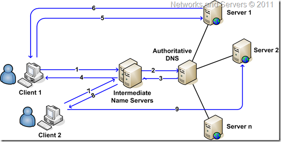
DNS load balancing is a popular yet simple approach to balancing server requests and consists basically in creating multiple DNS entries in the DNS record for the domain meaning  that the authoritative DNS server contains multiple “A” records for a single host.

Let’s imagine we want to balance the load on www.mywebsite.com, and we have three web servers with IP addresses of 64.13.192.120, 64.13.192.121, and 64.13.192.122 respectively, each is running a complete copy of the website, so no matter which server a request is directed to, the same response is provided.

To implement this, simply create the following DNS entries:

www.mywebsite.com    64.13.192.120
www.mywebsite.com    64.13.192.121
www.mywebsite.com    64.13.192.122

When a DNS request comes to the DNS server to resolve the domain name, it might give out one of the server IP addresses based on scheduling strategies, such as simple round-robin scheduling or geographical scheduling thus redirecting the request to one of the servers in a server group. Once the domain is resolved to one of the servers, subsequent requests from the clients using the same local caching DNS server are sent to the same server but request coming from other local DNSs will be sent to another server. This process is known as Round Robin DNS (RRDNS).

DNS Load Balancing

Load Balancing (IV)

Hardware based load balancing


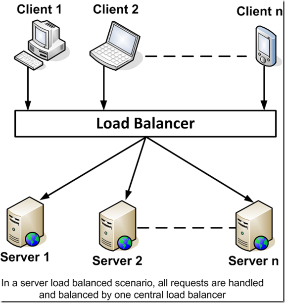
A hardware load-balancing device, also known as a layer 4-7 router, is a computer appliance that is used to split network load across multiple servers based on factors such as CPU processor utilization, the number of connections or the overall server performance.


The use of an this kind of appliances minimizes the probability that any particular server will be overwhelmed and optimizes the bandwidth available to each computer or terminal. In addition, the use of an hardware load-balancing device can minimize network downtime, facilitate traffic prioritization, provide end-to-end application monitoring, provide user authentication, and help protect against malicious activity such as Denial-of-Service (DoS) attacks.


The basic principle is that network traffic is sent to a shared IP called a virtual IP (VIP), or listening IP and this address is attached to the load balancer. Once the load balancer receives a request on this VIP it will need to make a decision on where to send it and this decision is normally controlled by a load balancing algorithm, a server health check or a rule set.


The request is then sent to the appropriate server and the server will produce a response that, depending on the type of load balancer in use, will be sent either back to the load balancer, in the case of a Layer 7 device, or more typically with a Layer 4 device, directly back to the end user (normally via its default gateway).
In the case of a proxy based load balancer, the request from the web server can be returned to the load balancer and manipulated before being sent back to the user. This manipulation could involve content substitution or compression and some top end devices offer full scripting capability.


Load Balancing Algorithms


Load balancers use different algorithms to control traffic and with the specific goal of intelligently distribute load and/or maximize the utilization of all servers within the cluster.


Random Allocation


In a random allocation, the traffic is assigned to any server picked randomly among the group of destination servers. In such a case, one of the servers may be assigned many more requests to process while the other servers are sitting idle. However, on average, each server gets an approximately equal share of the load due to the random selection. Although simple to implement it can lead to the overloading of one server or more while under-utilization of others.

Load Balancing (III)

Before we go any deeper into the abyss of all the techniques and algorithms used in the load balancing world it is important to clarify some concepts and notions and take a look at the most used load balancing terminology. The target audience of this blog is supposed to know what the OSI Model is and therefore I won’t even bother to explain what the layers are...  

Server health checking


Server health checking is the ability of the load balancer to run a test against the servers to determine if they are providing service:


  • Ping: This is the most simple method, however it is not very reliable as the server can be up whilst the web service could be down;

  • TCP connect:  This is a more sophisticated method which can check if a service is up and running like a service on port 80 for web. i.e. try and open a connection to that port on the real server;

  • HTTP GET HEADER: This will make a HTTP GET request to the web server and typically check for a header response such as 200 OK;

  • HTTP GET CONTENTS:  This will make a HTTP GET and check the actual content body for a correct response. Can be useful to check a dynamic web page that returns 'OK' only if some application health checks work i.e. backend database query validates. This feature is only available on some of the more advanced products but is the superior method for web applications as its will check that the actual application is available.

Layer-2 Load Balancing


Layer-2 load balancing (also referred as link aggregation, port aggregation, ether channel or gigabit ether channel port bundling) is to bond two or more links into a single, higher-bandwidth logical link. Aggregated links also provide redundancy and fault tolerance if each of the aggregated links follows a different physical path.

Load Balancing (II)

Client Based Load Balancing


It might be easier to make the client code and resources highly available and scalable than to do so for the servers; serving non-dynamic content requires fewer server resources. Before going into the details, let us consider a desktop application that needs to connect to servers on the internet to retrieve data. If our theoretical desktop application generates more requests to the remote server than it can handle, we will need a load balancing solution.


Server based load balancing

Instead of letting the client know of only one server from which to retrieve data, we can provide many servers—s1.mywebsite.com, s2.mywebsite.com, and so on. The desktop client randomly selects a server and attempts to retrieve data. If the server is not available, or does not respond in a preset time period, the client can select another server until the data is retrieved. Unlike web applications—which store the client code (JavaScript code or Flash SWF) on the same server that provides data and resource—the desktop client is independent of the server and able to load balance servers from the client side to achieve scalability for the application.

Client based load balancing

Load Balancing (I)

Load Balancing


The steady growth of the Internet is causing many performance problems, including low response times, network congestion and disruption of services either caused by normal system overload or by cyber attacks (DDoS). The most widely used solution to minimize or solve these problems in Load Balancing.

Load balancing is dividing the amount of work that a computer has to do between two or more computers so that more work gets done in the same amount of time and, in general, all users get served faster.

Load Balancing (sometimes also referred as to Network Load Balancing or Server Load Balancing) can also be described as the process of distributing service requests across a group of servers. This addresses several requirements that are becoming increasingly important in networks:

  • Increased scalability: When many content-intensive applications scale beyond the point where a single server can provide adequate processing power, it is increasingly important to have the flexibility to deploy additional servers quickly and transparently to end-users;


  • High performance: The highest performance is achieved when the processing power of servers is used intelligently. An advanced load balancing infrastructure can direct end-user service requests to the servers that are least busy and therefore capable of providing the fastest response time;


  • High availability and disaster recovery: The third benefit of load balancing is its ability to improve application availability. If an application or server fails, load balancing can automatically redistribute end-user service requests to other servers within a server cluster or to servers in another location;


On the Internet, companies whose Web sites get a great deal of traffic usually use load balancing. When a single Web Server machine isn’t enough to handle the traffic in a Web site it’s time to look into building a Web Farm that uses multiple machines on the network acting as a single server. In a web farm, services or applications can be installed onto multiple servers that are configured to share the workload. This type of configuration is a load-balanced cluster which scales the performance of server-based programs, such as a Web server, by distributing client requests across multiple servers.

High Availability – Networks (II)

Redundant Protocols

 
If you read the previous posts, your network already has redundant links and now you must decide how packets on the network will select their paths and avoid loops. This isn't a new problem; redundant paths have been addressed by protocols like Spanning Tree Protocol (STP) at Layer 2 and routing protocols like Open Shortest Path First (OSPF) at Layer 3. But these protocols can take 40 seconds or more to resolve and converge and this is unacceptable for critical networks, especially those with real-time applications like VoIP and video.
 
STP is a link management protocol that provides path redundancy while preventing undesirable loops in the network. For an Ethernet network to function properly, only one active path can exist between two stations. This protocol should be used in situations where you want redundant links, but not loops. Redundant links are as important as backups in the case of a failover in a network. A failure of your primary router activates the backup links so that users can continue to use the network. Without STP on the bridges and switches, such a failure can result in a loop.
 
To provide path redundancy, STP defines a tree that spans all switches in an extended network and forces certain redundant data paths into a standby (blocked) state. If one network segment in the STP becomes unreachable, or if STP costs change, the spanning-tree algorithm reconfigures the spanning-tree topology and reestablishes the link by activating the standby path.
 
An upgraded version of STP called RSTP (Rapid Spanning Tree 802.1w) cuts the convergence time of STP to about one second. One disadvantage to RSTP (and STP) is that only one of the redundant links can be active at a time in an "active standby" configuration another is that STP when changes the active path to another router, so the gateway addresses of the clients must change as well. To avoid these problems, you must run Virtual Router Redundancy Protocol (VRRP) along with STP and RSTP on your routers, which emulates one virtual router address for the core routers and takes about three seconds to fail over.
 
The advantage of using VRRP is that you gain a higher availability for the default path without requiring configuration of dynamic routing or router discovery protocols on every end host. VRRP routers viewed as a "redundancy group" share the responsibility for forwarding packets as if they "owned" the IP address corresponding to the default gateway configured on the hosts. One of the VRRP routers acts as the master and others as backups; if the master router fails, a backup router becomes the new master. In this way, router redundancy is always provided, allowing traffic on the LAN to be routed without relying on a single router.
 
But because VRRP and RSTP work independently, it's possible VRRP will designate one router as master and RSTP would determine the path to the backup router as the preferred path. Worst case, this means if the backup VRRP router receives traffic, it will immediately forward it to the master router for processing, adding a router hop.